
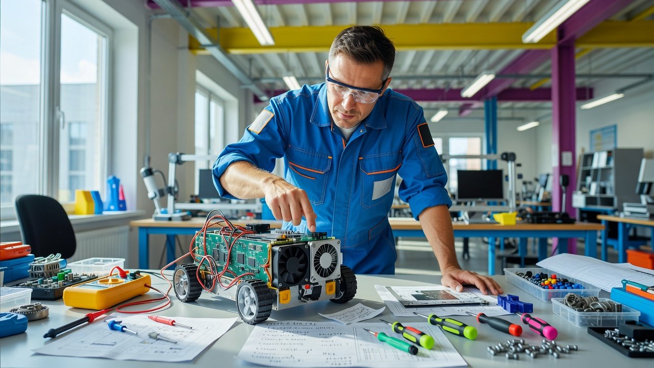
Best practices center on layout before components: plan airflow paths early, avoid sealed zones around heat sources, and preserve fan intake/exhaust clearances. Then use heat pipes, interface materials, or liquid cooling only where the architecture supports them. Dynamic fan control and integrated cooling channels add efficiency, but they cannot fix a blocked path.
Forty millimeters of clearance can decide whether your robot needs a fan upgrade, a heat pipe, or nothing at all.
Thermal design starts with geometry, not hardware
That sounds absurd until you picture what usually happens in a compact build. A motor driver, a compute board, a battery pack, and a fan all fit on paper. Then a bracket shifts, a cable bundle thickens, a cover closes, and the hot parts end up sitting in little private weather systems. Air enters the enclosure, but not where the heat is. The fan spins, but mostly stirs the wrong pocket. By the time temperatures rise on the bench, the conversation has narrowed to bigger heatsinks, faster fans, or some heroic liquid loop.
That is backwards. The decisive thermal choices in compact robots often happen before the first component is fixed in place. Thermal management starts as geometry. It starts with paths, gaps, surfaces, and escape routes. Cooling parts matter, of course, but they work well only when the layout gives heat somewhere to go.
This is the part many teams learn late, because cooling hardware feels concrete. You can buy a fan. You can spec a heat pipe. You can add a pad. Airflow planning feels less tangible, almost like housekeeping. Yet the most powerful move is usually the least glamorous one: plan the airflow path from the outset, avoid sealed zones around heat-generating components, and preserve intake and exhaust clearances near fans. Do that early, and the whole thermal problem shrinks. Miss it, and every later fix gets more expensive, heavier, and harder to package.
Two layouts, two thermal outcomes
Imagine a small mobile robot with two obvious hot spots: a compute module and a motor driver. Now imagine two versions of the same machine.
In the first, the compute module sits near an intake path, the motor driver has a direct conduction route to structure, and the fan has clear space to pull in air and throw it out. The cable harness runs around the airflow channel instead of through it. The enclosure includes vents where pressure can actually move air across hot surfaces. Nothing fancy has been added. The robot simply has a route for heat.
In the second, the same parts are packed by convenience. The driver board ends up behind the battery. The compute module sits in a corner pocket closed by a cover. The fan faces a nearby wall, with barely any intake clearance. Cables drape across the only real exhaust route. On the CAD screen, the difference looks trivial. On the bench, one machine runs warm and predictable. The other develops local hot spots, then thermal throttling, then the familiar debate about whether to add "better cooling."
The phrase local hot spot matters here. Compact robots rarely fail because the whole interior reaches one uniform temperature. They fail because one component sits in stagnant air or because one thermal interface is poor. A sealed zone around a heat source is the quiet villain in many designs. Once you create that pocket, every watt stays trapped longer. Then you end up compensating with more hardware for a problem caused by placement.
This is why thermal architecture belongs beside kinematics and power distribution in the first layout pass. It is not a finishing step. It is a routing problem, as real as wire routing and as unforgiving as collision checking.
Heat pipes and integrated cooling in tight spaces
You can see the same principle in the parts people reach for when space gets tight. Heat pipes are a good example. They sound like a bolt-on rescue, but their real strength appears when they are treated as part of the structure, not decoration after the fact. Heat pipes have no moving parts, high effective thermal conductivity, and an operating range from -268°C to 3229.9°C. That range is so broad it almost distracts from the practical point, which is simpler: they let you move heat away from a crowded hot zone without adding another motor, another fan, or another failure mode.
Even better, the geometry has evolved to suit compact machines. Spiral heat pipes and micro heat pipes with diameters under 2 mm are designed to fit tight robot layouts. That matters because compact robots usually do not lack cooling ideas. They lack room. A micro heat pipe can snake through a build where a larger heatsink simply cannot live.
But here is the catch. A heat pipe still needs somewhere useful to dump the heat. If it moves heat from a sealed pocket to another sealed pocket, you have only relocated the problem. If it connects a hot component to a chassis member with decent exposure, or to an area with active airflow, then it becomes transformative. The component is clever. The architecture decides whether that cleverness cashes out.
A more dramatic version shows up in harsher environments. One design for welding robots used a sealed cavity with an embedded heat pipe system paired with compressed air to clear dust while maintaining thermal efficiency. That is a strong reminder that thermal design is never only about maximum cooling. It is about cooling under actual operating constraints. Dust, splash, vibration, confined joints, and moving end effectors all change what "best" means. In a dirty environment, open airflow may create its own problem. Then a sealed approach, carefully engineered, becomes the right answer. Again, system design comes first.
Fans, control, and the myth of 'just add a fan'
This is also why the naive rule, "just add a fan," fails so often. Fans help, but only inside a coherent path. A fan pressed against an obstruction or starved for intake clearance cannot do much. Worse, it can trick you into thinking the thermal issue has been addressed because something is spinning and making noise. In compact robots, dead air is often a layout problem wearing the costume of a component problem.
Control matters too. Even when airflow is physically sound, a fixed fan strategy leaves performance on the table. Fan control can be integrated into system firmware so speed adjusts dynamically based on temperature sensors. That sounds modest, but it changes the robot from a static thermal object into a responsive one. Under light load, you avoid unnecessary power draw and dust ingestion. Under a burst load, you get extra cooling when it matters instead of all the time. Yet firmware control only helps after the air path exists. Software cannot command air through a blocked vent.
The same pattern repeats when designs move beyond air. Liquid cooling feels like a leap into a different class of system, and sometimes it is justified. In robotic end effectors, Hanon Systems combines liquid cooling with advanced heat exchanger designs. The company also uses lightweight aluminum construction with integrated cooling channels and smart thermal control valves that regulate coolant flow from real-time temperature. That is serious thermal engineering, not an improvised add-on.
Notice what makes it work. The cooling channels are integrated. The material choice matters. The control valves respond to actual temperature. The heat exchanger design is part of the assembly. Nobody stumbled into that result by stuffing a pump into an already overheated package. The lesson is not that every compact robot needs liquid cooling. Most do not. The lesson is that when cooling gets advanced, integration gets even more important.
Microchannel heat exchangers make the same point with a number attached. In tight spaces, liquid cooling with microchannel heat exchangers can reduce temperatures by 20 to 30°C. That is a large drop. It can rescue a design that would otherwise throttle or fail. But microchannels do not erase bad layout. They reward good layout. You still need room for flow paths, for interfaces, for serviceability, and for the mechanical consequences of tubing, channels, and seals.
Interface materials and the architecture rule
Material choices often look like the "small" part of thermal design, but in compact robots small parts matter because they live exactly where the thermal bottlenecks are. Graphene-based thermal films offer conductivity up to 5,000 W/m·K. Thermal conductive tapes and thermal interface pads are also used in humanoid robots. These are not dramatic components. They do not announce themselves. Yet they can close the gap between a hot device and the structure meant to carry its heat away.
Still, even here, the architecture rules. A superb thermal film attached to a poorly placed component gives you a more efficient route into a bad thermal neighborhood. An interface pad between a processor and a lid helps only if that lid can actually spread or shed the heat. Good materials amplify a good path. They do not invent one.
This is the turn that matters in practice. Engineers often treat thermal management as a stack of remedies, from fan to heatsink to heat pipe to liquid loop. The real stack starts earlier: placement, path, interface, control, then component. By the time you are shopping for stronger cooling hardware, much of the meaningful thermal design may already be frozen.
That is why layout tools deserve more respect in thermal work. AI-driven design tools are being used to optimize layouts for heat dissipation. The interesting part is not the phrase AI. The interesting part is what is being optimized: geometry, adjacency, paths, congestion. In other words, the exact decisions many teams still make by convenience, habit, or the order parts arrived on the bench.
A simple heat map: three failure patterns to look for
This does not require exotic software to start thinking clearly. You can do a surprising amount with a simple heat map sketch of your own design. Mark every heat source. Mark every intake and exhaust opening. Draw the likely air route, not the route you hope exists. Then look for three failure patterns.
First, sealed zones. Any heat-generating component trapped in a cavity with no real exchange path should make you uneasy. Second, fan starvation. If a fan intake or exhaust sits close to a wall, cover, cable bundle, or neighboring board, its rated performance may be fantasy. Third, broken conduction paths. If a hot part touches structure through poor interfaces, thin air gaps, or awkward standoffs, heat will linger where it starts.
Once you see the design this way, several decisions become easier. Move the hottest parts toward paths, not corners. Keep vents aligned with actual flow instead of placing them where they look symmetrical. Reserve space around fans early, before brackets and harnesses consume it. Use heat pipes when they can bridge from cramped hot spots to useful sinks. Use interface materials where they complete a conduction route. Reach for liquid cooling when the heat density and packaging justify the added system complexity, especially where integrated channels and compact exchangers can pay off.
One honest note on where to learn more from this site itself: it does not offer a dedicated thermal management course, though the closest practical offerings are Computer Vision for Robotics and Autonomous Systems, Isaac Lab: Custom Reinforcement Learning Environments, and LLM + VLM Integration: Multimodal AI Systems.
The important thing, though, is not another abstract checklist. It is what you do with the robot already on your bench or the CAD assembly open on your screen. Map the heat sources and airflow paths in your current design. Find the sealed zones. Check whether intake and exhaust are actually clear. Reposition one hot board if you can. Add vents before adding hardware. Give the fan room to breathe before asking it to work harder.
A compact robot rarely overheats because it lacked one more cooling part. It overheats because heat had nowhere believable to go. So when you look at your next layout, what is the first trapped pocket you can eliminate before it becomes a permanent climate?
FAQ
Why does thermal management in compact robots start with layout?
In compact builds, hot components can end up in sealed zones or dead air pockets, making every later cooling fix more expensive and less effective. Planning airflow paths, gaps, and escape routes early shrinks the entire thermal problem.
What are the most common thermal design mistakes in compact robots?
Three failure patterns dominate: sealed zones around heat sources, fan starvation from blocked intake/exhaust, and broken conduction paths due to poor interfaces or air gaps. These often look fine on CAD but cause hotspots on the bench.
When should you use heat pipes in a compact robot?
Heat pipes work best when they move heat from a crowded hot zone to a useful sink like an exposed chassis member or an area with active airflow. Micro heat pipes under 2 mm diameter fit tight layouts, but they cannot fix a sealed pocket by themselves.
Is liquid cooling necessary for compact robots?
Most compact robots do not need liquid cooling. It is justified when heat density and packaging demand it, especially with integrated channels and microchannel heat exchangers that can reduce temperatures by 20–30°C. But liquid cooling still requires good layout for flow paths and serviceability.
Can dynamic fan control replace good airflow design?
No. Firmware-controlled fans adjust speed based on temperature sensors, saving power and reducing dust, but software cannot push air through a blocked vent. A coherent physical airflow path must exist first.
Questions left? Get in touch →